Sunday, March 2, 2014

ir test

IR Test (Insulation Resistance Test)

The Insulation Resistance Test consists in measuring the Insulation resistance of a device under test, while phase and neutral are short circuited together. A megohmmeter (also called insulation resistance tester, teraohmmeter) is then used to measure the ohmic value of an insulator under a direct voltage of great stability.
To measure a high value resistance, techniques for measuring a low value current are used. A constant voltage source is applied to the resistance to be measured and the resulting current is read on a highly sensitive ammeter circuit that can display the resistance value.


File:Megger tester.jpg

The insulation resistance test seeks to measure the resistance of the insulation or dielectric. In this test, a voltage is applied to the insulation with the purpose of measuring the current which flows through it. Technicians can then use Ohms law to calculate the resistance by dividing the voltage by the current to get the resistance. Since the current measured will be small, in milliamps or microamps, the resistance will be large, which is typical for an insulator.


The measured resistance is intended to indicate the condition of the insulation or dieletric between two conductive parts, where the higher the resistance, the better the condition of the insulation. Ideally, the insulation resistance would be infinite, but as no insulators are perfect, leakage currents through the dielectric will ensure that a finite (though high) resistance value is measured.
Cable Fault Locators, Surge Generators (Thumpers) 

Surge generator cable fault locators ("thumpers") provide pre-location and pinpoint cable fault location. Cable fault prelocation using ICE (Impulse Current Method) is preferred for extensive underground cable fault location and pinpointing cable faults in water damaged cable joints.  Precise location of cable faults through surge generator fault locators (cable thumping) is very quick and limits expensive excavation by pinpoint accuracy.

Prelocation of Cable Faults with Surge Generators - Methods & Features 
 Impulse Current Method 

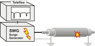
Surge generator ignites an arc at the cable fault which creates a travelling wave 
between the fault and the surge generator. The TDR Teleflex displays this transient wave which indicates the distance to the cable fault. A linear coupler for the impulse current method is installed in all surge generators with an output energy of 1000 Joules or more - this method of cable fault location can be useful for all high resistance cable faults, testing on wet cables, cable joints and also for fault location within long paper lead (PILC) cable networks.

SEBA KMT Impulse Current Method


ARM Arc Reflection Method 

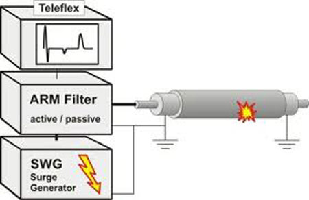
High resistive cable faults and intermittent faults can easily be located with the ARM Method - if the cable fault resistance is too high for direct measurement with a TDR Teleflex, a surge generator provides a low resistance arc at the fault which is then clearly located by the Teleflex like a low resistance fault via an ARM Filter. The TDR Teleflex shows a comparison of the traces with and without the arc - it is an easy, clear and precise method and therefore the most commonly used cable fault locating procedure today. ARM Filters are also available as separate instruments - M219 (inductive) and LSG300 (resistive). An active Arc Reflection Filter LSG 3E provides an extra 2kV power supply and capacitor. The SPG 32 surge generator features a built-in LSG300 filter.


Pinpointing Cable Faults 

For a precise location of the cable fault it is essential to confirm its position along the cable after prelocation with TDR measurement or any HV fault locating methods. Seba KMT surge generators have a time controlled surge output - it allows a periodical discharge into the cable for acoustic locating of the flash-over at the fault with an adequate ground microphone and receiver. 

Combined Acoustic and Magnetic Method 

The Digiphone measures the time difference between the magnetic signal of the surge current and the slower acoustic sound of the flash-over travelling through the ground. The display shows the time delay as indication of cable fault distance and the magnetic field strength as indication of the actual cable position. This means that a low number showing a short time delay indicates a short distance to the fault - this system will also work in noisy environment, cable ducts and for cable faults under paved surfaces

SEBA KMT Combined Acoustic and Magnetic Method

Cable Thumping Explained..............

 When a high voltage supply is applied to a faulted cable the resulting high-current arc makes a noise audible above ground. While this method eliminates the sectionalising methods need to cut and joint cables it has its own drawback. Cable thumping requires a current on the order of tens of thousands of amps at voltages as high as 25kV to make an underground noise loud enough to hear above ground. The heating from this high current often causes some degradation of the cable insulation. If the cable fault engineer is proficient in the cable thumping method damage can be limited by reducing the power sent through the cable to the minimum required to conduct the test. While moderate cable testing may produce no noticeable effects, sustained or frequent cable testing can cause the cable insulation to degrade to an unacceptable condition. Many cable fault locating experts accept some insulation damage for two reasons: 1) when cable thumping time is minimal, so is the cable insulation damage; 2) there is no existing technology (or combination of technologies) that can entirely replace cable thumping. 

Tuesday, February 25, 2014

Week 2 (Day 2)

- Attend the meeting which held every morning at 8am by team pencawang
- Today, we are going to do earthing at P/E Sungai Gau.
- Before that, we have to shut down P/E Simpang Caruk Puting and P/E Sungai Gau.
- The process of shutting down P/E Simpang Caruk Puting and P/E Sungai Gau will caused blackout to the consumer who live around Simpang Caruk Puting and Sungai Gau.
To make sure the electricity supplied to consumer won't be interrupted, we have to on (closed circuit) normal off point (NOP) at P/E simpang pulai.
- It means that the P/E simpang pulai will temporary supply electricity to consumer who live around Simpang Caruk Puting and Sungai Gau.
- Then, we can start doing earthing at P/E Sungai Gau.


- The copper cables have been stolen. We are here to reconnect the copper cables.


====================================================================


 IPC ( Isolated Piercing Connector)

- Connect cable to cable 


==================================================


schematic diagram KG AWAH

===================================================

-In order to prevent damage, each station along the network is protected with circuit breakers or fuses which will turn off power in the event of a short circuit. 

- Auto Recloser is a circuit breaker equipped with a mechanism that can automatically close the breaker after it has been opened due to a fault. ---

- Reclosers are used on overhead distribution systems to detect and interrupt momentary faults. 

-The control system for a recloser allows a selected number of attempts to restore service after adjustable time delays. 

-For example a recloser have 3 "fast" reclose operations with a few seconds delay, then a longer delay and one reclose; if the last attempt is not successful, the recloser will lock out and require human intervention to reset. 

Monday, February 24, 2014

Week 2 (Day 1)

- Attend TNB stuff gathering which held every monday at 8am.


- I introduced myself as a trainee in front of all the stuff TNB Temerloh.
- After the meeting, I followed team pencawang to stor pencawang.


- After this, we heading to Stesen Suis  Maxis at lanchang,pahang.
- Stesen Suis Maxis used to connect one substation to another substation. 
- It is same as P/E, the difference is stesen suis dont have transformer.
- Normally Stesen Suis Maxis located at non housing area.


- We are here to replace the new cable because we got report that the cable has been stolen.


- After finish replacing cable, we go to P/E KG PUNJONG.
-In this P/E, the transformer is not connected to feeder piller but a black box.
- The black box has the same function as the feeder piller.
- The difference is the feeder piller mostly used in housing area while black box mostly used in non-housing area.
- The cost for black box is cheaper.


- En. Zahhari explained to me the four important step to shut down a P/E 
1) Matikan (push to trip Circuit breaker)
2) Asingkan ( earth switch push to right)
3) Buktikan Mati (test on transformer)
4) Bumikan (Earth ON)
- After doing all the maintainence job, make sure we EARTH OFF it.


- Then, we go to SSU Lanchang.


- Battery (30V) for SSU
- Battery (110V) for PMU and PPU
- Battery is used to supply electricity to Switch gear (from transformer)


- When the main P/E having fault and cause breakdown,the other two P/E will be affected (break down),then bus station will switch on. 
- Then other two P/E will recover from breakdown but the main P/E still in break down condition.


===================================================================


- When customer complain (the light blinking),the possible condition is the transformer voltage drop.
- To solve it , We adjust the OLTC (off load tab changer) manually  to increase the voltage.
-off load tab changer for every substation except PPU
- PPU using on load tab changer (Automatically adjusted)


There are 3 main things we need to understand; generation,transmission and distribution.


the function of the generation is to provide total power needed.they are connected at common point called bus.

while transmission is important to transfer electric energy from generating units at various location to distribution system which ultimately supplies the load.

next is the distribution part, which connects the distribution substations to consumer's service-entrance equipment.


Saturday, February 22, 2014

Week 1 (Day 5)


- Today, I sit in the office and Encik Zahhari (Ketua Pasukan Pencawang) give me an infrared survey report.
- He asked me to read the report and figure it out.
- I learned how to differentiate from the infrared picture whether there are problem occur at the compartment/equipment.


Condition Monitoring System

-Before the problem or accident happen (i.e Flash Over), the best way (least-cost approach) is to monitor the condition of the substation.
The condition of substation can be monitor using Infrared technology.
Infrared technology:
- Service provider could asses the condition of the electrical power equipment under 'live condition'.

-This is very important as the infrared scanning operation will not disrupt the present supply of electricity to the respective clients.


The Basic Principle
  1. Each object has its own 'heat capability'.
  2. When the object is worm/hot, it produces radiation.
  3. The radiation can be quantified in term of frequency.
  4. The object is hotter ~ the higher the radiation~the higher the frequency intensity.
  5. This frequency - detected by infrared sensor and sends the data over the infrared system processor.
  6. The infrared system processor will subsequently process the data and projecting an infrared image on the screen.


CONDITION 1 :  On Monitoring


CONDITION 2 : On Monitoring


CONDITION 3 : Further Investigation