The Insulation Resistance Test consists in measuring the Insulation resistance of a device under test, while phase and neutral are short circuited together. A megohmmeter (also called insulation resistance tester, teraohmmeter) is then used to measure the ohmic value of an insulator under a direct voltage of great stability.
To measure a high value resistance, techniques for measuring a low value current are used. A constant voltage source is applied to the resistance to be measured and the resulting current is read on a highly sensitive ammeter circuit that can display the resistance value.

The insulation resistance test seeks to measure the resistance of the insulation or dielectric. In this test, a voltage is applied to the insulation with the purpose of measuring the current which flows through it. Technicians can then use Ohms law to calculate the resistance by dividing the voltage by the current to get the resistance. Since the current measured will be small, in milliamps or microamps, the resistance will be large, which is typical for an insulator.
The measured resistance is intended to indicate the condition of the insulation or dieletric between two conductive parts, where the higher the resistance, the better the condition of the insulation. Ideally, the insulation resistance would be infinite, but as no insulators are perfect, leakage currents through the dielectric will ensure that a finite (though high) resistance value is measured.


Cable Fault Locators, Surge Generators (Thumpers)
Surge generator cable fault locators ("thumpers") provide pre-location and pinpoint cable fault location. Cable fault prelocation using ICE (Impulse Current Method) is preferred for extensive underground cable fault location and pinpointing cable faults in water damaged cable joints. Precise location of cable faults through surge generator fault locators (cable thumping) is very quick and limits expensive excavation by pinpoint accuracy.
Prelocation of Cable Faults with Surge Generators - Methods & Features
Impulse Current Method
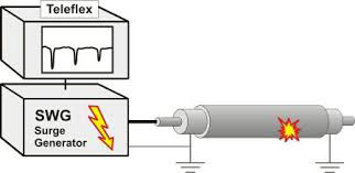
Surge generator ignites an arc at the cable fault which creates a travelling wave
between the fault and the surge generator. The TDR Teleflex displays this transient wave which indicates the distance to the cable fault. A linear coupler for the impulse current method is installed in all surge generators with an output energy of 1000 Joules or more - this method of cable fault location can be useful for all high resistance cable faults, testing on wet cables, cable joints and also for fault location within long paper lead (PILC) cable networks.

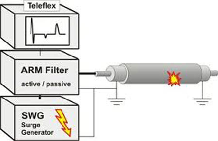
ARM Arc Reflection Method
High resistive cable faults and intermittent faults can easily be located with the ARM Method - if the cable fault resistance is too high for direct measurement with a TDR Teleflex, a surge generator provides a low resistance arc at the fault which is then clearly located by the Teleflex like a low resistance fault via an ARM Filter. The TDR Teleflex shows a comparison of the traces with and without the arc - it is an easy, clear and precise method and therefore the most commonly used cable fault locating procedure today. ARM Filters are also available as separate instruments - M219 (inductive) and LSG300 (resistive). An active Arc Reflection Filter LSG 3E provides an extra 2kV power supply and capacitor. The SPG 32 surge generator features a built-in LSG300 filter.

Pinpointing Cable Faults
For a precise location of the cable fault it is essential to confirm its position along the cable after prelocation with TDR measurement or any HV fault locating methods. Seba KMT surge generators have a time controlled surge output - it allows a periodical discharge into the cable for acoustic locating of the flash-over at the fault with an adequate ground microphone and receiver.
Combined Acoustic and Magnetic Method
The Digiphone measures the time difference between the magnetic signal of the surge current and the slower acoustic sound of the flash-over travelling through the ground. The display shows the time delay as indication of cable fault distance and the magnetic field strength as indication of the actual cable position. This means that a low number showing a short time delay indicates a short distance to the fault - this system will also work in noisy environment, cable ducts and for cable faults under paved surfaces

Cable Thumping Explained..............
When a high voltage supply is applied to a faulted cable the resulting high-current arc makes a noise audible above ground. While this method eliminates the sectionalising methods need to cut and joint cables it has its own drawback. Cable thumping requires a current on the order of tens of thousands of amps at voltages as high as 25kV to make an underground noise loud enough to hear above ground. The heating from this high current often causes some degradation of the cable insulation. If the cable fault engineer is proficient in the cable thumping method damage can be limited by reducing the power sent through the cable to the minimum required to conduct the test. While moderate cable testing may produce no noticeable effects, sustained or frequent cable testing can cause the cable insulation to degrade to an unacceptable condition. Many cable fault locating experts accept some insulation damage for two reasons: 1) when cable thumping time is minimal, so is the cable insulation damage; 2) there is no existing technology (or combination of technologies) that can entirely replace cable thumping.